INTRODUCTION TO CONTROL SYSTEM
1.1introduction
Engineering ( engineering ) is concerned with understanding and controlling materials and energy / power in nature for the benefit of man . Control systems engineer ( control systems engineer ) associated with things to understand and control the parts of the environment are often called as a system , to produce an economical product for humans . Understanding and control (understanding and controlling) are two aspects complementary , because effective control system requires an understanding
and proper modeling of a system . Contemporary challenges of control engineer is how to model and control system of the modern ,
complex , and interconnected , such as traffic control systems , chemical processes , and robotic systems .
Some definitions :
Controlled - variable ( Controlled Variable ) : quantity or condition measured and controlled . Generally it is the output of the system .
- Manipulated variables ( Manipulated Variable ) : quantity or condition altered / manipulated by the controller to change the value of the variable controlled .
- Plant : equipment , a collection of machine parts functioning which together aim to perform an operation .
- Process : every operation is controlled , such as chemical processes , economics , biology , etc. .
- System : a combination of components that work together to achieve a certain goal .
- Disorders ( disturbances ) : signals that affect the value of the output of the system .
If the interference is generated from within the system , referred to as internal disturbances, while those coming from outside the system is referred to as external disturbances.
disturbances, while those coming from outside the system is referred to as external disturbances.
Control system (control system) is an interconnection of components forming a system configuration that aims to generate a response desired. The basis for the analysis of a system is linear system theory, which assuming causality (cause-effect) for the components of a system. So that a component or process to be controlled can be expressed by a block as shown in Figure.
Input-output relationship expressed causality of the process, which declare a process of input signal to produce an output signal. a open-loop control system using the controller or actuator to obtain desired response, such as in Figure 1.2. In the open-loop system, the propulsion equipment (actuating device) is used to control the process directly, without the use of feedback (feedback).
Examples of open-loop control system is operated with a microwave oven certain period of time. Closed-loop control system using an additional measurement of the actual output to be compared with the desired output response. measurement output is called the feedback signal. Figure 1.3 shows an example of simple closed-loop control system.
Perbedaan antara output yang diinginkan dengan output aktual disebut sebagai error, yang selanjutnya akan di adjust (disesuaikan) oleh peralatan pengendali. Output dari peralatan pengendali menyebabkan aktuator memodulasi proses untuk mengurangi error. Sistem yang diperlihatkan pada gambar adalah sistem kendali negative feedback, karena output dikurangkan dari input dan perbedaannya digunakan sebagai sinyal input ke peralatan pengendali. Contoh sistem kendali closed-loop adalah seorang pengendara mobil yang melihat lokasi/posisi di jalan dan membuat penyesuaian yang tepat/seharusnya.
Open-loop vs. closed-loop
The advantage of the closed-loop control system is that the presence of feedback make the system response relatively unaffected by external disturbances and variations of internal system parameters. Stability of the system, the open-loop control system was made easier because of the stability system is not a major problem. But stability is a major issue the closed - loop control system , where the error will resolve error causes oscillations that lead to instability .
For systems where the input is known in advance and there is no interference ,then you should use an open - loop control system . Closed - loop control system have an advantage if there is interference that can not be predicted and / or variety of system components which can not be predicted .
Number of components used in the closed - loop control system more than those used in open - loop control system . Thus , the control system closed - loop generally need a large cost and energy . To summarize , the open - loop control system has the following main advantages :
- Construction is simple and easy to maintain
- It is cheaper than the closed - loop control system - its
- There is no stability problems
- Suitable for use if the system output is difficult to measure or measuring output is not economically feasible. ( Example : the washing system , will quite expensive to provide quality laundry gauge , namely cleanliness of the clothes are washed ) . While the main disadvantages of the open - loop control system are :
- Disorders and calibration changes caused the error , and will output different from the desired
- To maintain the quality of the output , recalibration should be carried out from time to time .
1.2 HISTORY OF AUTOMATIC CONTROL
The first feedback system to be invented in modern Europe was the temperature regulator of Cornelis Drebbel (1572-1633) from Holland .
Dennis Papin (1647-1712) invented the first pressure regulator for steam boilers in 1681 . Papin 's pressure regulator was a form of safety regulator similar to a pressure - cooker valve .
The first automatic feedback controller used in an industrial process is generally agreed to be James Watt’s flyball governor, developed in 1769 for controlling the speed of a steam engine. The all-mechanical device is shown in Figure.
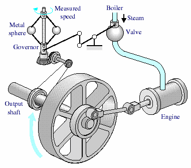
The first historical feedback system, claimed by Russia, is the water-level float regulator said to have been invented by I. Polzunov in 1765. The level regulator system is shown in Fig. 1.6. The float detects the water level and controls the valve that covers the water inlet in the boiler.
1868: J. C. Maxwell formulates a mathematical model for a governor control of a steam engine.
1913: Henry Ford’s mechanised assembly machine introduced for automobile production.
1927: H.W. Bode analyses feedback amplifiers.
1932: H. Nyquist develops a method for analysing the stability of systems.
1952: Numerical control (NC) developed at Massachusetts Institute of Technology for control of machine-tool axes.
1954: George Devol develops “programmed article transfer,” considered to be the first industrial robot design.
1960: First robot introduced, based on Devol’s designs.
1961: Robots used for tending die-casting machines.
1970: State-variable models and optimal control developed.
1980: Robust control system design widely studied.
1990: Export-oriented manufacturing companies emphasize automation.
1994: Feedback control widely used in automobiles. Reliable, robust systems demanded in manufacturing.
1997: First ever autonomous rover vehicle, known as Sojourner, explores the Martian surface.
1998-2003: Advances in micro- and nanotechnology. First intelligent micromachines are developed and functioning nanomachines are created.
1.3TIPE FEEDBACK CONTROL SYSTEM
Based on the method of analysis and design of control systems can be classified as the following :
linear and nonlinear control system : The system in practice is nonlinear . system linear control is an ideal model that is used to simplify analysis and design .
The system does not change with time ( time - invariant ) and time-varying ( time -varying ) : time - invariant system is a system in which the parameters of the system control does not change with time during the operation of the system . almost
all elements of the system in practice which has changed / varied to of time .
continuous and discrete control systems : continuous system is a system where their signals is a function of continuous time variable . whereas discrete signal is a system where sinnyal - signal digital signal merupkan .
System single variable ( single variable ) and many variables ( multivariable ) : Single variable system has a single input , single output ( SISO : Single input single output ) . Many systems have a lot of input variables and output ( MIMO : Multi- input , multi- output ) , as in the picture.
EXAMPLE 1.4 CONTROL SYSTEM
1.4.1 car steering control system
Block diagram of the steering control system is shown in Figure (a).Position (car trips) compared to the desired position measurement actual to generate an error as in Figure (b). This measurement is obtained of visual and tactile feedback (body movement). There is also an additional feedback from the steering wheel by hand (sensor). A typical response to the direction of travel shown in the picture.
FIGURE - (a)Automobile steering control system
(b) The driver uses the difference between the actual and the desired direction of travel to
generate a controlled adjustment of the steering wheel
(c) Typical direction-of-travel response
1.4.2 System level control tank
Closed-loop control system (manual) to control the liquid level in a tank is shown in Figure 1.9. As the input is the reference level of the liquid desired (reference is remembered by the operator). Control equipment is operator, and the sensor is a visual sensor. Operators compare the actual level to the desired level and opening or closing the valve (actuator), which will adjust the discharge rate, thereby maintaining the fluid at desired level.
1.4.3 Three-Axis Control System
Figure 1.10 shows a three-axis control system for wafer inspection semiconductors. This system uses special motors to drive each
axis to the desired position on the xyz axes. The purpose of the system control here is to get a smooth and accurate movement on each axis.
1.4.4 Power Plant
Today, control of the power plant to produce the minimum exhaust emissions be important. Large power plant requires an automatic control system take into account the relationship between process variables and power production. Power plant This generally has 90 or more variables are manipulated to control coordinated. Figure 1.11 shows the block diagram of the system simplified.
1.4.5 Model control system of national income
Simple model of national income control system is shown in Figure. This model is useful to help analysts understand the impact of regulation government and government spending dynamical
1.5 FUTURE CONTROL SYSTEM
Ongoing objective of the control system is to provide a flexible to - late and higher autonomy . Two kinds of approaches to achieve goals is shown in Figure 1:13 . Nowadays , industrial robots can be said autonomous enough - once programmed , in general no longer needed intervention humans . But because of the limitations of sensors , robotic systems have the flexibility which is limited to adapting to a changing work environment ; increase sensing system is a motivation in research in the field of computer vision .
Meanwhile, the control system is highly adaptive , but depends on the supervision humans . The robotic system made for adaptive task through development of sensor feedback . Field of research that concentrates on intelligence artificial ( AI = artificial intelligent ) , the integration of sensors , computer vision , and programming CAD / CAM will make the system more universal and economical .
Control system is moving towards autonomous operation as an increase of human control . Research on supervisory control , human-machine interface , computer database management aims to reduce the limitations of operator and increase operator efficiency. Many research activities are conducted in the field of robotics and control systems and aims to reduce costs implementation and extend the application. This includes also improved methods communication and programming languages.
The theory, practice, and application of automatic control is a large, exciting, disclipine engineering and extremely useful.
1.6 DESIGN EXAMPLE:
1.6.1 ROTATING DISK SPEED CONTROL
Many modern devices that use a rotating disc at a speed constant. For example, a CD player, hard disk, etc. require a rotation speed constant despite the variations in the motor and other components change. Our objective is to design a control system which ensures that the disc speed actual speed of disc rotation speed is in the range desired . We will review the system without and with feedback . To play a disc , we choose a DC motor as an actuator for the motor DC can produce speeds in accordance with the applied voltage . to input voltage to the motor , we can use an amplifier to produce the required voltage .
Open - loop control system is shown in Figure 1:14 ( a) . The system uses battery source to generate the required voltage . the voltage further amplified and applied to the motor . Block diagram of the control system of open - This loop depicting control equipment , actuators and processes are shown in Figure.
To obtain feedback system , we need a sensor . One of the sensors are can be used is a tachometer that produces an output proportional to velocity axis. So that the closed - loop control system can be made as to figure . Block diagram of the closed - loop system is shown in Figure . Voltage error resulting from the difference between the input voltage and the voltage tachometer .
We can expect that the closed - loop control system on the image will better than the open - loop control system in Figure 1.14 , because the feedback system will respond and act to minimize error .
FIGURE
(a)Open-loop control (without feedback) of the speed of a turntable
(b)Block diagram model
(a) Closed-loop control (with feedback) of the speed of a turntable
(b) Block diagram model
1.6.2 CONTROL INSULIN DELIVERY SYSTEM
Control system has been used in the biomedical field to produce a system automated drug delivery to patients implanted (implant) in the patient's body. Automatic systems can be used to regulate blood pressure, blood glucose levels, and heart rate. One example is a system for controlling the levels blood glucose will be discussed below.
Blood sugar and insulin concentration for healthy people is shown in Figure . The system must be able to produce insulin made from a container that grafted / implanted in diabetic patients . So that the control objectives are :
Control objectives :
Designing a system to regulate blood sugar concentration of diabetic patients with insulin control . With reference to the drawings 1:16 , then the next step is to define variables were controlled .
Controlled variables :
Blood sugar concentration .
Controller design specifications :
Provide blood glucose levels for diabetic patients whose glucose levels following healthy people . With a given destination , controlled variables , and specifications , we can designing the initial configuration of the control system . With the control system of open - loop , it is necessary to producing a signal which can be programmed at the beginning of ( preprogrammed ) and mini bike pump to adjust the insulin infusion as shown in Figure ( a) . While the closed - loop control system using sensor to measure glucose level and compare it with the level desirable , so that the motor will turn on the pump if necessary , such as
shown in Figure ( b ) .
FIGURE The blood glucose and insulin levels for a healthy person.
FIGURE (a)Open loop control; (b) Closed-loop control
Referensi :
1.Richard C. Dorf, Robert H. Bishop, 2008, Modern Control System 11th edition, Pearson Prentice Hall.
2.Katsuhiko Ogata, 2002, Modern Control Engineering 4th edition, Prentice Hall.
Rabu, 30 Oktober 2013
BASIC PROGRAMMING C + +
INTRODUCTION C + +
Talking about C and C + + as the language of its predecessor, C an n pemrograma including mid-level language. Creator of C was Brian W. Kernighan and Dennis M. Ritchie in 1972. C is a programming language structured program divides into a number of blocks (sub-program). The aim is to facilitate the making and program development. Programs written with C easily moved from one type of machine to another. it is because of the standardization of C is ANSI (American National Standards Institute) the reference compiler makers C.
C + + was created a decade after C. C + + was created by Bjarne Stroustroup from Bell Laboratories, AT & T in 1983. At first C + + is named "A better C". Name of C + + itself named by Rick Mascitti. The + sign + derived from the increment operator in C language.
C is a privilege because this language supports OOP (Object Oriented Programming). The main goal is to improve the manufacturing C productivity of programmers in creating applications. Most experts agree that OOP and C can reduce the complexity of the program, especially comprises more than 10,000 lines, it can even increase productivity 2X of C, Pascal and Basic.
B. Object Oriented Programming (OOP)
OOP basic idea is to combine data and functions to access the data into a unified unit. This unit is known as an object. as an illustration for mempurmudah understand it, the object may actually reflect patterns of everyday human labor. An object can be described as departments within a business firm, for example, the department.
-sale
-accounting
-personnel
Division of the department in the company is an attempt to facilitate operation of the company. As an illustration, if you are a manager sales in the central office wants to know the data of the salesmen at the branch office,what do you do? Steps you traveled certainly not come to branches and look for these data. To ease your task Your pretty secretary told to ask for information. The issue of how and who find not your business. Analogy with it, if someone intends to use the object, it simply send a message to the object and the object itself is going to handle it.
C. program C
C programs can be created using any text editor or editor as well as the compiler. The main program extension (. CPP). At the time of compilation The main program along with the header files (. h) will be translated by compiler into an object file (. OBJ). Furthermore this object files together with other object files and library files (. LIB) linked together by a linker. The result is a file (. EXE) executable.
D. Compiler C + +
C + + compiler that has been circulating in the market such as Microsoft C / C + + and Visual C + +. Both are from Microsoft. While international Borland also issued Turbo C + + and Borland C + +.
RECOGNITION PROGRAM C + +
A. Hello World
Here is an example C + + program that is simple
# include
void main ()
{
cout << "Hello world. \ n";
}
Once compiled and Dirun, the result is Hello World appears on the screen.
B. Function main ()
Program C + + is not be separated from a function / function. it is as is characteristic of OOP. A C + + program has at least one function the main (). This function is the beginning of the main program. Writing main () is the name of the function, while the parts are enclosed with {and} are called block (body function). In this case an early sign {} block and is marks the end of the block. As in Pascal, the Pascal {identical with BEGIN, while synonymous with} END. Command void means that the function main () does not return a value / value.
Way of writing the function main () is not absolute as above. Here's how another writing
# include
int main ()
{
cout << "Hello world. \ n";
return 0;
}
C. Statement
Command cout << "Hello world. \ n "; was one example statement. The command is used to print text on the screen. Each statement must end with;
It is important to note here that the C + + program is Case Sensitive, meaning uppercase and lowercase letters are considered different.
The \ n is used to move the line.
D. file Header
In the example above , called iostream.h header file . The header file necessary for court orders can be executed . If the header file removed , then the error will occur . To access the header file , use command # include , or # include " file header " . In a program may involve more than one header file .
Note :
Command cout << " Hello world . \ N " ; can be replaced with printf ( " Hello world . \ n " ) ;
But to be able to use printf required header file stdio.h
E. Removing Screen
In C + + , the command clrscr ( ), is used to remove / clean up the screen . This command will be run after adding the header file conio.h
# include
# include
void main ( )
{
clrscr ( ) ;
cout << " Hello world . \ n " ;
}
F. comment
You can add comments to your program . The following style for add comments .
/ / ----------------------------------
/ / This is the first remarked
/ / ----------------------------------
or
/ * ----------------------------------
I remarked that this was the first
---------------------------------- * /
Thank you for reading the article BASIC PROGRAMMING C + + is hopefully a little useful for the reader as well.
Regards .. andregk.blogspot.com :)
INTRODUCTION C + +
Talking about C and C + + as the language of its predecessor, C an n pemrograma including mid-level language. Creator of C was Brian W. Kernighan and Dennis M. Ritchie in 1972. C is a programming language structured program divides into a number of blocks (sub-program). The aim is to facilitate the making and program development. Programs written with C easily moved from one type of machine to another. it is because of the standardization of C is ANSI (American National Standards Institute) the reference compiler makers C.
C + + was created a decade after C. C + + was created by Bjarne Stroustroup from Bell Laboratories, AT & T in 1983. At first C + + is named "A better C". Name of C + + itself named by Rick Mascitti. The + sign + derived from the increment operator in C language.
C is a privilege because this language supports OOP (Object Oriented Programming). The main goal is to improve the manufacturing C productivity of programmers in creating applications. Most experts agree that OOP and C can reduce the complexity of the program, especially comprises more than 10,000 lines, it can even increase productivity 2X of C, Pascal and Basic.
B. Object Oriented Programming (OOP)
OOP basic idea is to combine data and functions to access the data into a unified unit. This unit is known as an object. as an illustration for mempurmudah understand it, the object may actually reflect patterns of everyday human labor. An object can be described as departments within a business firm, for example, the department.
-sale
-accounting
-personnel
Division of the department in the company is an attempt to facilitate operation of the company. As an illustration, if you are a manager sales in the central office wants to know the data of the salesmen at the branch office,what do you do? Steps you traveled certainly not come to branches and look for these data. To ease your task Your pretty secretary told to ask for information. The issue of how and who find not your business. Analogy with it, if someone intends to use the object, it simply send a message to the object and the object itself is going to handle it.
C. program C
C programs can be created using any text editor or editor as well as the compiler. The main program extension (. CPP). At the time of compilation The main program along with the header files (. h) will be translated by compiler into an object file (. OBJ). Furthermore this object files together with other object files and library files (. LIB) linked together by a linker. The result is a file (. EXE) executable.
D. Compiler C + +
C + + compiler that has been circulating in the market such as Microsoft C / C + + and Visual C + +. Both are from Microsoft. While international Borland also issued Turbo C + + and Borland C + +.
RECOGNITION PROGRAM C + +
A. Hello World
Here is an example C + + program that is simple
# include
void main ()
{
cout << "Hello world. \ n";
}
Once compiled and Dirun, the result is Hello World appears on the screen.
B. Function main ()
Program C + + is not be separated from a function / function. it is as is characteristic of OOP. A C + + program has at least one function the main (). This function is the beginning of the main program. Writing main () is the name of the function, while the parts are enclosed with {and} are called block (body function). In this case an early sign {} block and is marks the end of the block. As in Pascal, the Pascal {identical with BEGIN, while synonymous with} END. Command void means that the function main () does not return a value / value.
Way of writing the function main () is not absolute as above. Here's how another writing
# include
int main ()
{
cout << "Hello world. \ n";
return 0;
}
C. Statement
Command cout << "Hello world. \ n "; was one example statement. The command is used to print text on the screen. Each statement must end with;
It is important to note here that the C + + program is Case Sensitive, meaning uppercase and lowercase letters are considered different.
The \ n is used to move the line.
D. file Header
In the example above , called iostream.h header file . The header file necessary for court orders can be executed . If the header file removed , then the error will occur . To access the header file , use command # include
Note :
Command cout << " Hello world . \ N " ; can be replaced with printf ( " Hello world . \ n " ) ;
But to be able to use printf required header file stdio.h
E. Removing Screen
In C + + , the command clrscr ( ), is used to remove / clean up the screen . This command will be run after adding the header file conio.h
# include
# include
void main ( )
{
clrscr ( ) ;
cout << " Hello world . \ n " ;
}
F. comment
You can add comments to your program . The following style for add comments .
/ / ----------------------------------
/ / This is the first remarked
/ / ----------------------------------
or
/ * ----------------------------------
I remarked that this was the first
---------------------------------- * /
Thank you for reading the article BASIC PROGRAMMING C + + is hopefully a little useful for the reader as well.
Regards .. andregk.blogspot.com :)
Senin, 28 Oktober 2013
MAKING GUIDE Protel 99 SE PCB DESIGN USING EXPLORER
OPENING EARLY STEP Protel 99 SE
1.1 Initial steps to open protel 99 SE
Once the installation is complete we do, a subsequent step is an introduction to the software, so we did not encounter any significant obstacles at work in the process. The introduction of software here we emphasize brief introduction Protel 99 SE how to open, create a new database, create a new file.
First we open the first software Protel 99 SE by clicking Start ► Programs ► ► Protel 99 SE Protel 99 SE, then the appearance of Protel 99 SE or less as shown in the picture below :
Protel display a blank worksheet as shown in the figure above, before we start, from the above worksheet we will create a new database that will be used to design Schematic diagram to be a PCB, how to create a new database in the following way:
Click the File menu ► New, as shown in the figure below. It will display the New Design Database dialog box as shown in the figure below.
Fill the box with Design Storage Type "MS Access databese" and name the Database File Name "MyDesignCAD" and specify the Location Database by clicking Browse, as shown in the figure below, when finished click OK.
Design Explorer it will display as shown below , this is where we will make various types of files that are related to each other to form a database that is implemented on a desing and layout components . The next step after we know how to open protel is how we create a new file sebuat that will serve as editor - at each step TIPA performing tasks that we do . First we will create a file Schematic Diagram which we will use to draw the series which will we make as a PCB , the steps are as follows . Right click on any empty space in the area , it will display the menu as shown in the figure below , then click the New menu .
Once we select the New menu it will display a dialog box to confirm us to choose the type of file that will be created , as shown below , select the " Document Schematic " and continue by selecting OK
.
Document menu will appear as shown in the figure below, the Document menu will appear an icon of the file we have created, name the file with the name "Schematic Diagrams" and continue by pressing Enter, after that proceed to Double click on the icon is to open the worksheet Schematic Diagram, it will be displayed on the worksheet approximately Schematic Diagram drawn as shown below
To display the types and kinds of components that we will use later click the Browse menu, it will display a menu of components as shown in the figure below
In the picture above is shown the various types of components that have been supplied by Protel 99 SE we just click one of the components that we will use , and we can apply the worksheet by drag and drop . Here we demonstrated how to draw the Schematic Document , Choose one of the components that we will use , for example capacitor then click the Place button . Then the symbol of the capacitor will be automatically entered in the worksheet Schematic . If we want to enter symbols other components then do the same with the only difference in the way the name of the other symbols correspond to the name of the component , eg for resistors Resistor his name is , his name is transistor NPN / PNP , etc. .
Tool option provided by Protel 99 SE is very simple because it is very minimum but its usefulness is unbelievably complex , an example of the tool option from Protel .
To the left of the tool option that serves as a wire , line , bus , Polygon , Bus Entry , Eliptical Arc , Net Label , Bezier , Power Port , Annotation , Part , Text Frame , Sheet Symbol , Rectangle , Sheet Entry , Round Rectangle , Port , elipse , Luntion , Pie Part , No. Erc , Graphic Image , PCB Layout Directive , and Array Placement .
For the next option on the tool serves as a Document Manager , Document Open , Save , Print Setup , Zoom , Zoom Sch , Down Hierarchy , Cross probe , Selected Object , Object Deselect , Move , Drawing , Wiring , Run Dialog , Run Simulation , Remove Library , Place Part and Component Part Number increament For toolbar some of which serve as a standard tool that really should exist in any software , but there are some functions of the toolbar that is used by Protel to support such software , including Place , Design , Tool , Simulate , PLD , and Report . < Br >
DRAWING SCEMATICS
2.1 At the start Drawing Scematics
Next we will start by creating a schematic diagram that we will create the documents that we created earlier, here we will use some of the components such as capacitor, Resistors, Transistors, Doide, IC, etc..
The title sequence is that we will create DESIGNING AND MAKING EQUIPMENT DRYER Phaleria MICROCONTROLLER AT89C51. As seen in the picture below.
Open the worksheet Schematic Diagram with double click on the icon Schematic Diagram for Changing head Picture right click on the image head, select Document Options. Then remove the thugs in the Title box.
2.2 List Component
List of required components can be seen in the picture below.
2.3 Entering Component
After preparing the list of components needed, then the next we will incorporate the components into sheet schematics.
- To input capacitor (C), open the schematic then choose Browse miscellanious.lib 1. Place select a capacitor and then click on the image 2. To change the value double click on the component and then type the appropriate value of an existing column. Our love for capacitor values shown in Figure 3 below.
-For other components such as IC. To menginputnya have the same way with the above components. So after completion of the placement of the components above, we stayed between the legs synchronize according to existing image, until completion as shown in the figure below.
2.4 Assembling Components
Next we will assemble the components that we have had input, connect the resistor, capacitor, transistor, etc.. Use the tools PlaceWire to connect between the legs of the components like the picture below.
Bundle to be intact as shown in Figure.
MAKE PCB
3.1 Creating netlist
After we completed the schematics, the next step is to import them to the PCB. Previously we had to create a netlist first, how is the select tab select CREATE DESIGN NETLIST, then you will see a dialog box netlist creation and continued with OK.
3.2 Create PCB After creating the netlist then the next step is to make its PCB. Select the tab DESIGN> UPDATE PCB, then the dialog will appear as shown below.
After that we click on Execute UPDATE DESIGN. At the first look after you click Execute it will show a layout of components and pengawatannya. Then we set it as neat as possible to look like the picture below.
The next step is to set the RULES that we can set the width and the distance between the lines, to set us select the Design tab> Rules dialog will appear as shown below.
We can arrange clearance constraint or the distance between the hole component legs and place the line, we click properties. We can adjust according to our wishes on the minimum clearance just as the picture below. Then followed by OK.
We can also set the line width by selecting the width constraint is still at the design rules, select Properties, and set in accordance with our wishes and continued with OK.
When finished set the rules, then we will merounting earlier series by selecting the tab autorouter> All. It will mncul Autorouter setup dialog and then we select Route All. Like this picture.
The results after at rounting would like the image below.
The picture above is the finished PCB circuit consisting of a top layer and bottom layer.
We can also see the results in 3D images, as shown below.
3.3 Print-out Results Top Layer and Bottom Layer
The final step to get the print-out we select file> print / preview, the result looks like the image below.
• The print-out bottom layer
• The print-out top layer
• The print-out holes only
• The print-out Multi Layer PCB
Maybe an article about MAKING GUIDE Protel 99 SE PCB DESIGN USING EXPLORER can be useful for all readers. Thank
Regards andregk.blogspot.com :)
1.1 Initial steps to open protel 99 SE
Once the installation is complete we do, a subsequent step is an introduction to the software, so we did not encounter any significant obstacles at work in the process. The introduction of software here we emphasize brief introduction Protel 99 SE how to open, create a new database, create a new file.
First we open the first software Protel 99 SE by clicking Start ► Programs ► ► Protel 99 SE Protel 99 SE, then the appearance of Protel 99 SE or less as shown in the picture below :
Protel display a blank worksheet as shown in the figure above, before we start, from the above worksheet we will create a new database that will be used to design Schematic diagram to be a PCB, how to create a new database in the following way:
Click the File menu ► New, as shown in the figure below. It will display the New Design Database dialog box as shown in the figure below.
Fill the box with Design Storage Type "MS Access databese" and name the Database File Name "MyDesignCAD" and specify the Location Database by clicking Browse, as shown in the figure below, when finished click OK.
Design Explorer it will display as shown below , this is where we will make various types of files that are related to each other to form a database that is implemented on a desing and layout components . The next step after we know how to open protel is how we create a new file sebuat that will serve as editor - at each step TIPA performing tasks that we do . First we will create a file Schematic Diagram which we will use to draw the series which will we make as a PCB , the steps are as follows . Right click on any empty space in the area , it will display the menu as shown in the figure below , then click the New menu .
Once we select the New menu it will display a dialog box to confirm us to choose the type of file that will be created , as shown below , select the " Document Schematic " and continue by selecting OK
.
Document menu will appear as shown in the figure below, the Document menu will appear an icon of the file we have created, name the file with the name "Schematic Diagrams" and continue by pressing Enter, after that proceed to Double click on the icon is to open the worksheet Schematic Diagram, it will be displayed on the worksheet approximately Schematic Diagram drawn as shown below
To display the types and kinds of components that we will use later click the Browse menu, it will display a menu of components as shown in the figure below
In the picture above is shown the various types of components that have been supplied by Protel 99 SE we just click one of the components that we will use , and we can apply the worksheet by drag and drop . Here we demonstrated how to draw the Schematic Document , Choose one of the components that we will use , for example capacitor then click the Place button . Then the symbol of the capacitor will be automatically entered in the worksheet Schematic . If we want to enter symbols other components then do the same with the only difference in the way the name of the other symbols correspond to the name of the component , eg for resistors Resistor his name is , his name is transistor NPN / PNP , etc. .
Tool option provided by Protel 99 SE is very simple because it is very minimum but its usefulness is unbelievably complex , an example of the tool option from Protel .
To the left of the tool option that serves as a wire , line , bus , Polygon , Bus Entry , Eliptical Arc , Net Label , Bezier , Power Port , Annotation , Part , Text Frame , Sheet Symbol , Rectangle , Sheet Entry , Round Rectangle , Port , elipse , Luntion , Pie Part , No. Erc , Graphic Image , PCB Layout Directive , and Array Placement .
For the next option on the tool serves as a Document Manager , Document Open , Save , Print Setup , Zoom , Zoom Sch , Down Hierarchy , Cross probe , Selected Object , Object Deselect , Move , Drawing , Wiring , Run Dialog , Run Simulation , Remove Library , Place Part and Component Part Number increament For toolbar some of which serve as a standard tool that really should exist in any software , but there are some functions of the toolbar that is used by Protel to support such software , including Place , Design , Tool , Simulate , PLD , and Report . < Br >
DRAWING SCEMATICS
2.1 At the start Drawing Scematics
Next we will start by creating a schematic diagram that we will create the documents that we created earlier, here we will use some of the components such as capacitor, Resistors, Transistors, Doide, IC, etc..
The title sequence is that we will create DESIGNING AND MAKING EQUIPMENT DRYER Phaleria MICROCONTROLLER AT89C51. As seen in the picture below.
Open the worksheet Schematic Diagram with double click on the icon Schematic Diagram for Changing head Picture right click on the image head, select Document Options. Then remove the thugs in the Title box.
2.2 List Component
List of required components can be seen in the picture below.
2.3 Entering Component
After preparing the list of components needed, then the next we will incorporate the components into sheet schematics.
- To input capacitor (C), open the schematic then choose Browse miscellanious.lib 1. Place select a capacitor and then click on the image 2. To change the value double click on the component and then type the appropriate value of an existing column. Our love for capacitor values shown in Figure 3 below.
-For other components such as IC. To menginputnya have the same way with the above components. So after completion of the placement of the components above, we stayed between the legs synchronize according to existing image, until completion as shown in the figure below.
2.4 Assembling Components
Next we will assemble the components that we have had input, connect the resistor, capacitor, transistor, etc.. Use the tools PlaceWire to connect between the legs of the components like the picture below.
Bundle to be intact as shown in Figure.
MAKE PCB
3.1 Creating netlist
After we completed the schematics, the next step is to import them to the PCB. Previously we had to create a netlist first, how is the select tab select CREATE DESIGN NETLIST, then you will see a dialog box netlist creation and continued with OK.
3.2 Create PCB After creating the netlist then the next step is to make its PCB. Select the tab DESIGN> UPDATE PCB, then the dialog will appear as shown below.
After that we click on Execute UPDATE DESIGN. At the first look after you click Execute it will show a layout of components and pengawatannya. Then we set it as neat as possible to look like the picture below.
The next step is to set the RULES that we can set the width and the distance between the lines, to set us select the Design tab> Rules dialog will appear as shown below.
We can arrange clearance constraint or the distance between the hole component legs and place the line, we click properties. We can adjust according to our wishes on the minimum clearance just as the picture below. Then followed by OK.
We can also set the line width by selecting the width constraint is still at the design rules, select Properties, and set in accordance with our wishes and continued with OK.
When finished set the rules, then we will merounting earlier series by selecting the tab autorouter> All. It will mncul Autorouter setup dialog and then we select Route All. Like this picture.
The results after at rounting would like the image below.
The picture above is the finished PCB circuit consisting of a top layer and bottom layer.
We can also see the results in 3D images, as shown below.
3.3 Print-out Results Top Layer and Bottom Layer
The final step to get the print-out we select file> print / preview, the result looks like the image below.
• The print-out bottom layer
• The print-out top layer
• The print-out holes only
• The print-out Multi Layer PCB
Maybe an article about MAKING GUIDE Protel 99 SE PCB DESIGN USING EXPLORER can be useful for all readers. Thank
Regards andregk.blogspot.com :)
Sabtu, 16 Maret 2013
Rangkaian alarm dan lampu darurat pada saat listrik pada
Rangkaian alarm dan lampu darurat pada saat listrik padam
Rangkaian alarm dan lampu darurat pada saat padam ini secara permanen dicolokkan ke soket listrik sehingga baterai NI-CD akan terisi. Ketika terjadi pemadaman listrik, lampu otomatis menyala. Selain penerangan lampu, sebuah alarm suara dapat digunakan. Ketika pasokan listrik hidup kembali, lampu atau alarm akan mati (off). Switch melakukan fungsi “latch-up”, untuk memperpanjang pengoperasian lampu atau alarm bahkan ketika listrik hidup kembali.
Cara kerja: • Tegangan listrik berkurang menjadi sekitar 12V DC di terminal C2, dengan cara reaktansi C1 dan jembatan dioda (D1-D4). sehingga menghindari penggunaan transformator listrik.
• Trickle- pengisian arus untuk baterai B1 disediakan oleh rangkaian resistor R3, D5 dan LED hijau D6 yang juga memantau adanya pasokan listrik dan pengisian baterai yang benar.
• Q2 & Q3 membentuk self-latching pair yang mulai beroperasi ketika terjadi pemadaman listrik. Dalam kasus ini, Q1 bias menjadi positif, sehingga transistor ini berubah pada self-latching pair.
• Jika SW3 diatur seperti yang ditunjukkan dalam diagram rangkaian, lampu menyala melalui SW2, yang biasanya tertutup, jika diatur dengan cara lain, gelombang persegi audio frekuensi generator yang dibentuk oleh Q4, Q5, dan komponen terkait akan diaktifkan, dan memicu loudspeaker.
• Jika SW1 dibiarkan terbuka, ketika pasokan listrik dipulihkan lampu atau alarm terus beroperasi. Namun dapat dinonaktifkan dengan membuka switch utama SW2 on-off.
• Jika SW1 ditutup, pemulihan pasokan listrik mengakhiri dari operasi lampu atau alarm, dengan menerapkan bias positif ke basis Q2.
Komponen: R1; Resistor 220K 1/4W
R2: Resistor 470R 1/2W
R3: Resistor 1/4W 390R
R4: Resistor 1/4W 1K5
R5: Resistor 1R 1/4W
R6: Resistor 10K 1/4W
R7: Resistor 1/4W 330K
R8: Resistor 470R 1/4W
R9: Resistor 100R 1/4W
C1: Kapacitor Polyester 330nF 400V
C2: Kapacitor elektrolit 10ÂμF 63V
C3: Kapacitor Polyester 100nF 63V
C4: Kapacitor Polyester 10nF 63V
D1-D5: Dioda 1N4007 1A 1000V
D6: LED Hijau (bentuk bebas)
D7: Dioda 1N4148 75V 150mA
Q1, Q3, Q4: Transistor NPN BC547 45V 100mA
Q2, Q5: Transistor PNP BC327 45V 800mA
SW1, SW2: Switch SPST
SW3: Switch SPDT
LP1: 2.2V atau 2.5V 250-300mA Torch Lamp
Spkr 8 Ohm Loudspeaker
B1: 2.5V Baterai (dua baterai AA NI-CD yang dapat diisi ulang dihubungkan secara seri)
PL1: Steker listrik
Catatan:
• Tutup SW2 setelah rangkaian dicolokkan.
Sumber : www. http://komponenelektronika.org/rangkaian-alarm-dan-lampu-darurat.htm
Rangkaian alarm dan lampu darurat pada saat padam ini secara permanen dicolokkan ke soket listrik sehingga baterai NI-CD akan terisi. Ketika terjadi pemadaman listrik, lampu otomatis menyala. Selain penerangan lampu, sebuah alarm suara dapat digunakan. Ketika pasokan listrik hidup kembali, lampu atau alarm akan mati (off). Switch melakukan fungsi “latch-up”, untuk memperpanjang pengoperasian lampu atau alarm bahkan ketika listrik hidup kembali.
Cara kerja: • Tegangan listrik berkurang menjadi sekitar 12V DC di terminal C2, dengan cara reaktansi C1 dan jembatan dioda (D1-D4). sehingga menghindari penggunaan transformator listrik.
• Trickle- pengisian arus untuk baterai B1 disediakan oleh rangkaian resistor R3, D5 dan LED hijau D6 yang juga memantau adanya pasokan listrik dan pengisian baterai yang benar.
• Q2 & Q3 membentuk self-latching pair yang mulai beroperasi ketika terjadi pemadaman listrik. Dalam kasus ini, Q1 bias menjadi positif, sehingga transistor ini berubah pada self-latching pair.
• Jika SW3 diatur seperti yang ditunjukkan dalam diagram rangkaian, lampu menyala melalui SW2, yang biasanya tertutup, jika diatur dengan cara lain, gelombang persegi audio frekuensi generator yang dibentuk oleh Q4, Q5, dan komponen terkait akan diaktifkan, dan memicu loudspeaker.
• Jika SW1 dibiarkan terbuka, ketika pasokan listrik dipulihkan lampu atau alarm terus beroperasi. Namun dapat dinonaktifkan dengan membuka switch utama SW2 on-off.
• Jika SW1 ditutup, pemulihan pasokan listrik mengakhiri dari operasi lampu atau alarm, dengan menerapkan bias positif ke basis Q2.
Komponen: R1; Resistor 220K 1/4W
R2: Resistor 470R 1/2W
R3: Resistor 1/4W 390R
R4: Resistor 1/4W 1K5
R5: Resistor 1R 1/4W
R6: Resistor 10K 1/4W
R7: Resistor 1/4W 330K
R8: Resistor 470R 1/4W
R9: Resistor 100R 1/4W
C1: Kapacitor Polyester 330nF 400V
C2: Kapacitor elektrolit 10ÂμF 63V
C3: Kapacitor Polyester 100nF 63V
C4: Kapacitor Polyester 10nF 63V
D1-D5: Dioda 1N4007 1A 1000V
D6: LED Hijau (bentuk bebas)
D7: Dioda 1N4148 75V 150mA
Q1, Q3, Q4: Transistor NPN BC547 45V 100mA
Q2, Q5: Transistor PNP BC327 45V 800mA
SW1, SW2: Switch SPST
SW3: Switch SPDT
LP1: 2.2V atau 2.5V 250-300mA Torch Lamp
Spkr 8 Ohm Loudspeaker
B1: 2.5V Baterai (dua baterai AA NI-CD yang dapat diisi ulang dihubungkan secara seri)
PL1: Steker listrik
Catatan:
• Tutup SW2 setelah rangkaian dicolokkan.
Sumber : www. http://komponenelektronika.org/rangkaian-alarm-dan-lampu-darurat.htm
Minggu, 18 November 2012
PENGHITUNG KODE WARNA PADA RESITOR
Selamat malam sahabat, pada malam yang dingin ini saya akan sharing untuk yang pengen mengetahui nilai resistansi pada resistor secara instan nih sahabat. Oke langsung saja ya, dengan judul "Penghitung kode warna pada resitor" ini berwujud Exel sahabat, jadi sahabat bisa langsung memasukkan kode warna yang tertera pada tubuh resistor itu dan seketika bisa langsung diketahui nilai resistansinya. Baiklah sahabat, langsung di download aja ya, klik disini.
Enjoy.. :)
Selasa, 07 Agustus 2012
MENGENAL, MERAWAT, DAN MEMPERBAIKI PENANAK NASI ( RICE COOKER )
PENANAK NASI LISTRIK (ELECTRIC RICE COOKER)
Alat penanak nasi yang banyak dipakai pada rumah tangga umum menyebutnya rice cooker. Dan karena waktu penanakannya cukup lama ya kira-kira 1,5 jam, alat ini disebut juga sebagai slow cooker. Peralatan ini memungkinkan digunakan pada rumah tangga, karena pemakaian dayanya mulai dari 350 watt, 500 watt, 800 watt, dan seterusnya. Inilah salah satu bentuk PENANAK NASI ( electric rice cooker ).
Bagaimana KONTRUKSINYA ?
Pada dasarnya peralatan ini terdiri dari bagian pokok :
1. Pan bagian dalam, untuk menempatkan beras yang akan ditanak, terbuat dari logam/aluminiumnya yang dilapisi bahan anti lengket.
2. Elemen pemanas
Pada rice cooker tertentu pemanas ini dililitkan pada bagian samping pan bagian dalam. Untuk jenis seperti ini, apabila elemen rusak dapat diperbaiki. Namun pada kebanyakan rice cooker yang diperdagangkan sekarang. elemen pemanas ditempatkan dalam bagian/pipa yang solid/permanen, sehingga bila rusak sukar diperbaiki.
3. Rumah bagian luar (out case) sebagai pelindung dari pan bagian dalam dan elemen. Pada bagian ini biasanya terdapat saklar dan terminal untuk kabel tenaga. Saklar umumnya mempunyai 2 kedudukan yaitu kedudukan cooking dan warm.
4. Kabel tenaga
Kabel ini biasanya terdiri dari tusuk kontak untuk ke sumber listrik dan kontra steker untuk keterminal pada peralatan. Bila peralatan tidak dipakai, kabel dapat dilepas dan disimpan terpisah.
5. Tutup
Kebanyakan rice cooker mempunyai dua buah tutup yaitu satu tutup untuk pan bagian dalam dan satu lagi tutup bagian atas yang dilengkapi dengan klem.
Seperti gambar ini
Serta bagaimana perawatan Rice Cooker ?
Perawatan pada rice cooker relatif ringan, perawatan dilakukan terhadap fisik, kelistrikan dan sedikit bagian mekanik.
Perawatan terhadap fisik peralatan ialah dalam bentuk pembersihan bagian-bagian peralatan seperti pan bagian dalam, rumah bagian luar. Membersihkan bagian dalam cukup dengan air dan sabun/vim. Sedang untuk bagian luar agar tidak mudah berkarat harus selalu kering dan bila mungkin diberi bahan anti karat atau bila catnya sudah rusak dilakukan pengecatan kembali.
Pemeliharaan kelistrikannya antara lain dijaga agar kabel tenaga tidak sering tertekuk dan perhatikan saklar, apabila nasi telah masak, pastikan bahwa saklar dalam posisi off atau warm.
Setiap kali akan menggunakan yakinkan bahwa tidak ada benda lain yang berada dibagian dalam antara pan dengan bagian dasar rice cooker yang dapat mengganggu proses menanak nasi.
Dan bagaimana cara memperbaikinya ?
Bagian yang memungkinkan kerusakan pada rice cooker antara lain :
6. Kabel tenaga, putus atau isolasi terkupas. Cara perbaikannya bila memungkinkan diperbaiki/diisolasi pada bagian yang rusak, tetapi kalau kabel sudah cukup tua dan pendek lebih baik diganti baru.
7. Saklar, yang kerusakannya pada bagian mekanik seperti pegas dan kontakkontaknya. Karena model saklarnya tidak umum dijual dipasaran, bila rusak memerlukan perbaikan atau dimodifikasi.
8. Elemen pemanas, kerusakan elemen pemanas biasanya disebabkan oleh kesalahan tegangan, dimana biasanya dipakai untuk tegangan 110 volt kemudian dipakai pada tegangan 220 volt. Penyebab lainnya adalah karena kurangnya pemeliharaan, sehingga pada bagian elemen atau bagian dasar dari rice cooker berkarat, sehingga pelindung elemen rusak dan elemennya putus atau terhubung singkat dengan badan. Untuk merek tertentu elemen pemanas ini ada dijual satu set, tetapi pada kebanyak merk kerusakan elemen susah diperbaiki
9. Pengatur panas, alat ini dilengkapi dengan pengatur/pembatas panas dari bimetal, kerusakan pada bimetal dapat menyebabkan rice cooker tidak panas atau panas menjadi terlalu tinggi. Untuk ini bimetal perlu diperiksa dan diset ulang atau diperbaiki.
Terimakasih telah membaca artikel ini dan semoga bermanfaat buat anda-anda semua :)
Alat penanak nasi yang banyak dipakai pada rumah tangga umum menyebutnya rice cooker. Dan karena waktu penanakannya cukup lama ya kira-kira 1,5 jam, alat ini disebut juga sebagai slow cooker. Peralatan ini memungkinkan digunakan pada rumah tangga, karena pemakaian dayanya mulai dari 350 watt, 500 watt, 800 watt, dan seterusnya. Inilah salah satu bentuk PENANAK NASI ( electric rice cooker ).
Bagaimana KONTRUKSINYA ?
Pada dasarnya peralatan ini terdiri dari bagian pokok :
1. Pan bagian dalam, untuk menempatkan beras yang akan ditanak, terbuat dari logam/aluminiumnya yang dilapisi bahan anti lengket.
2. Elemen pemanas
Pada rice cooker tertentu pemanas ini dililitkan pada bagian samping pan bagian dalam. Untuk jenis seperti ini, apabila elemen rusak dapat diperbaiki. Namun pada kebanyakan rice cooker yang diperdagangkan sekarang. elemen pemanas ditempatkan dalam bagian/pipa yang solid/permanen, sehingga bila rusak sukar diperbaiki.
3. Rumah bagian luar (out case) sebagai pelindung dari pan bagian dalam dan elemen. Pada bagian ini biasanya terdapat saklar dan terminal untuk kabel tenaga. Saklar umumnya mempunyai 2 kedudukan yaitu kedudukan cooking dan warm.
4. Kabel tenaga
Kabel ini biasanya terdiri dari tusuk kontak untuk ke sumber listrik dan kontra steker untuk keterminal pada peralatan. Bila peralatan tidak dipakai, kabel dapat dilepas dan disimpan terpisah.
5. Tutup
Kebanyakan rice cooker mempunyai dua buah tutup yaitu satu tutup untuk pan bagian dalam dan satu lagi tutup bagian atas yang dilengkapi dengan klem.
Seperti gambar ini
Serta bagaimana perawatan Rice Cooker ?
Perawatan pada rice cooker relatif ringan, perawatan dilakukan terhadap fisik, kelistrikan dan sedikit bagian mekanik.
Perawatan terhadap fisik peralatan ialah dalam bentuk pembersihan bagian-bagian peralatan seperti pan bagian dalam, rumah bagian luar. Membersihkan bagian dalam cukup dengan air dan sabun/vim. Sedang untuk bagian luar agar tidak mudah berkarat harus selalu kering dan bila mungkin diberi bahan anti karat atau bila catnya sudah rusak dilakukan pengecatan kembali.
Pemeliharaan kelistrikannya antara lain dijaga agar kabel tenaga tidak sering tertekuk dan perhatikan saklar, apabila nasi telah masak, pastikan bahwa saklar dalam posisi off atau warm.
Setiap kali akan menggunakan yakinkan bahwa tidak ada benda lain yang berada dibagian dalam antara pan dengan bagian dasar rice cooker yang dapat mengganggu proses menanak nasi.
Dan bagaimana cara memperbaikinya ?
Bagian yang memungkinkan kerusakan pada rice cooker antara lain :
6. Kabel tenaga, putus atau isolasi terkupas. Cara perbaikannya bila memungkinkan diperbaiki/diisolasi pada bagian yang rusak, tetapi kalau kabel sudah cukup tua dan pendek lebih baik diganti baru.
7. Saklar, yang kerusakannya pada bagian mekanik seperti pegas dan kontakkontaknya. Karena model saklarnya tidak umum dijual dipasaran, bila rusak memerlukan perbaikan atau dimodifikasi.
8. Elemen pemanas, kerusakan elemen pemanas biasanya disebabkan oleh kesalahan tegangan, dimana biasanya dipakai untuk tegangan 110 volt kemudian dipakai pada tegangan 220 volt. Penyebab lainnya adalah karena kurangnya pemeliharaan, sehingga pada bagian elemen atau bagian dasar dari rice cooker berkarat, sehingga pelindung elemen rusak dan elemennya putus atau terhubung singkat dengan badan. Untuk merek tertentu elemen pemanas ini ada dijual satu set, tetapi pada kebanyak merk kerusakan elemen susah diperbaiki
9. Pengatur panas, alat ini dilengkapi dengan pengatur/pembatas panas dari bimetal, kerusakan pada bimetal dapat menyebabkan rice cooker tidak panas atau panas menjadi terlalu tinggi. Untuk ini bimetal perlu diperiksa dan diset ulang atau diperbaiki.
Terimakasih telah membaca artikel ini dan semoga bermanfaat buat anda-anda semua :)
Senin, 16 April 2012
SATUAN LISTRIK
TEGANGAN LISTRIK DAN SATUANNYA
Dalam teori elektron telah dijelaskan bahwa arus listrik adalah perpindahan elektron dari satu zat ke zat yang lainnya. Jika muatan listrik dalam suatu zat terlampau banyak atau sedikit, maka pada benda itu akan timbul desakan yang akan mengakibatkan timbulnya perbedaan (tekanan). Perbedaan tekanan ini dalam teori listrik disebut TEGANGAN LISTRIK.
Untuk mengukur tinggi rendahnya tegangan dan beda tegangan kita menggunakan satuan VOLT atau dapat singkat dengan simbol V.
Volt berasal dari nama seorang sarjana kimia bangsa italia, yaitu ALESANDRO GLUSEPPE ANTONIO ANAS TASIO VOLTA (1755-1857) sebagai penemu elemen volta.
Tegangan listrik biasanya di tuliskan dengan notasi E. Seperti juga mata uang mempunyai angka pecahan, satuan listrik juga mempunyai angka satuan besar dan angka satuan yang lebih kecil satuan yang lebih tinggi dari volt adalah :
1 Kilo Volt = 1KV = 1000 V =103 V
1 Mega Volt = 1MV = 1.000.000 V = 106 V
Satuan yang lebih rendah dari volt adalah :
1 Mili Volt = 1mV = 0,001 V = 10-3 V
1 Micro Volt = 1µV = 0,000001 V = 10-6 V
Pecahan ini dalam pemakaian sehari-hari berlaku juga untuk satuan listrik lainya.
• Cara mengukur tegangan :
Sobat dapat melakukan percobaan ini sendiri di rumah atau di mana saja.
Tujuan :
a. Agar sobat dapat mengetahui bagaimana caranya mengukur tegangan arus listrik searah.
b. Agar sobat dapat mengetaui cara mempergunakan alt ukur listrik.
• Alat-alat yang digunakan :
a. Sebuah alat ukur yang disebut AVO meter.
b. Sebuah baterai kering 1,5 Vol.
• Cara mengukur (Lihat gambar)
Pertama-tama letakan batas ukur AVO meter pada skala dengan posisi DC, lalu tempelkan salah satu ujung kawat pengukur yang bertanda positif (+) pada kutub baterai, tempelkan ujung kawat yang bertanda negatif (-) pada kutub baterai lainya. Sekarang lihatlah jarum pada skala AVO meter. Jarum akan menunjuk pada angka yang sesuai dengan besarnya tegangan pada baterai, apabila penunjukan jarum terbalik maka tukarlah ujung kawat AVO meter, kemungkinan sobat salah meletakkan positif dan negatifnya.
Dalam teori elektron telah dijelaskan bahwa arus listrik adalah perpindahan elektron dari satu zat ke zat yang lainnya. Jika muatan listrik dalam suatu zat terlampau banyak atau sedikit, maka pada benda itu akan timbul desakan yang akan mengakibatkan timbulnya perbedaan (tekanan). Perbedaan tekanan ini dalam teori listrik disebut TEGANGAN LISTRIK.
Untuk mengukur tinggi rendahnya tegangan dan beda tegangan kita menggunakan satuan VOLT atau dapat singkat dengan simbol V.
Volt berasal dari nama seorang sarjana kimia bangsa italia, yaitu ALESANDRO GLUSEPPE ANTONIO ANAS TASIO VOLTA (1755-1857) sebagai penemu elemen volta.
Tegangan listrik biasanya di tuliskan dengan notasi E. Seperti juga mata uang mempunyai angka pecahan, satuan listrik juga mempunyai angka satuan besar dan angka satuan yang lebih kecil satuan yang lebih tinggi dari volt adalah :
1 Kilo Volt = 1KV = 1000 V =103 V
1 Mega Volt = 1MV = 1.000.000 V = 106 V
Satuan yang lebih rendah dari volt adalah :
1 Mili Volt = 1mV = 0,001 V = 10-3 V
1 Micro Volt = 1µV = 0,000001 V = 10-6 V
Pecahan ini dalam pemakaian sehari-hari berlaku juga untuk satuan listrik lainya.
• Cara mengukur tegangan :
Sobat dapat melakukan percobaan ini sendiri di rumah atau di mana saja.
Tujuan :
a. Agar sobat dapat mengetahui bagaimana caranya mengukur tegangan arus listrik searah.
b. Agar sobat dapat mengetaui cara mempergunakan alt ukur listrik.
• Alat-alat yang digunakan :
a. Sebuah alat ukur yang disebut AVO meter.
b. Sebuah baterai kering 1,5 Vol.
• Cara mengukur (Lihat gambar)
Pertama-tama letakan batas ukur AVO meter pada skala dengan posisi DC, lalu tempelkan salah satu ujung kawat pengukur yang bertanda positif (+) pada kutub baterai, tempelkan ujung kawat yang bertanda negatif (-) pada kutub baterai lainya. Sekarang lihatlah jarum pada skala AVO meter. Jarum akan menunjuk pada angka yang sesuai dengan besarnya tegangan pada baterai, apabila penunjukan jarum terbalik maka tukarlah ujung kawat AVO meter, kemungkinan sobat salah meletakkan positif dan negatifnya.
Langganan:
Postingan (Atom)