

1.1introduction
Engineering ( engineering ) is concerned with understanding and controlling materials and energy / power in nature for the benefit of man . Control systems engineer ( control systems engineer ) associated with things to understand and control the parts of the environment are often called as a system , to produce an economical product for humans . Understanding and control (understanding and controlling) are two aspects complementary , because effective control system requires an understanding and proper modeling of a system . Contemporary challenges of control engineer is how to model and control system of the modern , complex , and interconnected , such as traffic control systems , chemical processes , and robotic systems .
Some definitions :
Controlled - variable ( Controlled Variable ) : quantity or condition measured and controlled . Generally it is the output of the system .
- Manipulated variables ( Manipulated Variable ) : quantity or condition altered / manipulated by the controller to change the value of the variable controlled .
- Plant : equipment , a collection of machine parts functioning which together aim to perform an operation .
- Process : every operation is controlled , such as chemical processes , economics , biology , etc. .
- System : a combination of components that work together to achieve a certain goal .
- Disorders ( disturbances ) : signals that affect the value of the output of the system .
If the interference is generated from within the system , referred to as internal disturbances, while those coming from outside the system is referred to as external disturbances. disturbances, while those coming from outside the system is referred to as external disturbances.
Control system (control system) is an interconnection of components forming a system configuration that aims to generate a response desired. The basis for the analysis of a system is linear system theory, which assuming causality (cause-effect) for the components of a system. So that a component or process to be controlled can be expressed by a block as shown in Figure.

Input-output relationship expressed causality of the process, which declare a process of input signal to produce an output signal. a open-loop control system using the controller or actuator to obtain desired response, such as in Figure 1.2. In the open-loop system, the propulsion equipment (actuating device) is used to control the process directly, without the use of feedback (feedback).

Examples of open-loop control system is operated with a microwave oven certain period of time. Closed-loop control system using an additional measurement of the actual output to be compared with the desired output response. measurement output is called the feedback signal. Figure 1.3 shows an example of simple closed-loop control system.

Perbedaan antara output yang diinginkan dengan output aktual disebut sebagai error, yang selanjutnya akan di adjust (disesuaikan) oleh peralatan pengendali. Output dari peralatan pengendali menyebabkan aktuator memodulasi proses untuk mengurangi error. Sistem yang diperlihatkan pada gambar adalah sistem kendali negative feedback, karena output dikurangkan dari input dan perbedaannya digunakan sebagai sinyal input ke peralatan pengendali. Contoh sistem kendali closed-loop adalah seorang pengendara mobil yang melihat lokasi/posisi di jalan dan membuat penyesuaian yang tepat/seharusnya.

Open-loop vs. closed-loop
The advantage of the closed-loop control system is that the presence of feedback make the system response relatively unaffected by external disturbances and variations of internal system parameters. Stability of the system, the open-loop control system was made easier because of the stability system is not a major problem. But stability is a major issue the closed - loop control system , where the error will resolve error causes oscillations that lead to instability .
For systems where the input is known in advance and there is no interference ,then you should use an open - loop control system . Closed - loop control system have an advantage if there is interference that can not be predicted and / or variety of system components which can not be predicted .
Number of components used in the closed - loop control system more than those used in open - loop control system . Thus , the control system closed - loop generally need a large cost and energy . To summarize , the open - loop control system has the following main advantages :
- Construction is simple and easy to maintain
- It is cheaper than the closed - loop control system - its
- There is no stability problems
- Suitable for use if the system output is difficult to measure or measuring output is not economically feasible. ( Example : the washing system , will quite expensive to provide quality laundry gauge , namely cleanliness of the clothes are washed ) . While the main disadvantages of the open - loop control system are :
- Disorders and calibration changes caused the error , and will output different from the desired
- To maintain the quality of the output , recalibration should be carried out from time to time .
1.2 HISTORY OF AUTOMATIC CONTROL
The first feedback system to be invented in modern Europe was the temperature regulator of Cornelis Drebbel (1572-1633) from Holland .
Dennis Papin (1647-1712) invented the first pressure regulator for steam boilers in 1681 . Papin 's pressure regulator was a form of safety regulator similar to a pressure - cooker valve .
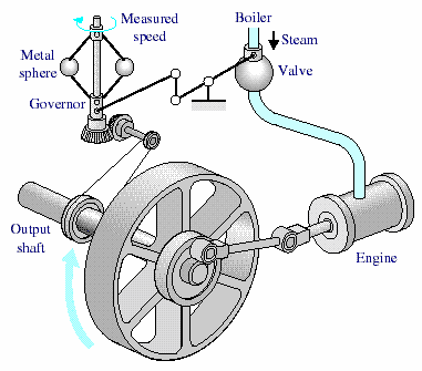
The first automatic feedback controller used in an industrial process is generally agreed to be James Watt’s flyball governor, developed in 1769 for controlling the speed of a steam engine. The all-mechanical device is shown in Figure.
The first historical feedback system, claimed by Russia, is the water-level float regulator said to have been invented by I. Polzunov in 1765. The level regulator system is shown in Fig. 1.6. The float detects the water level and controls the valve that covers the water inlet in the boiler.
1868: J. C. Maxwell formulates a mathematical model for a governor control of a steam engine.
1913: Henry Ford’s mechanised assembly machine introduced for automobile production.
1927: H.W. Bode analyses feedback amplifiers.
1932: H. Nyquist develops a method for analysing the stability of systems.

1952: Numerical control (NC) developed at Massachusetts Institute of Technology for control of machine-tool axes.
1954: George Devol develops “programmed article transfer,” considered to be the first industrial robot design.
1960: First robot introduced, based on Devol’s designs.
1961: Robots used for tending die-casting machines.
1970: State-variable models and optimal control developed.
1980: Robust control system design widely studied.
1990: Export-oriented manufacturing companies emphasize automation.
1994: Feedback control widely used in automobiles. Reliable, robust systems demanded in manufacturing.
1997: First ever autonomous rover vehicle, known as Sojourner, explores the Martian surface.
1998-2003: Advances in micro- and nanotechnology. First intelligent micromachines are developed and functioning nanomachines are created.
1.3TIPE FEEDBACK CONTROL SYSTEM
Based on the method of analysis and design of control systems can be classified as the following :
linear and nonlinear control system : The system in practice is nonlinear . system linear control is an ideal model that is used to simplify analysis and design .
The system does not change with time ( time - invariant ) and time-varying ( time -varying ) : time - invariant system is a system in which the parameters of the system control does not change with time during the operation of the system . almost all elements of the system in practice which has changed / varied to of time .
continuous and discrete control systems : continuous system is a system where their signals is a function of continuous time variable . whereas discrete signal is a system where sinnyal - signal digital signal merupkan .
System single variable ( single variable ) and many variables ( multivariable ) : Single variable system has a single input , single output ( SISO : Single input single output ) . Many systems have a lot of input variables and output ( MIMO : Multi- input , multi- output ) , as in the picture.

EXAMPLE 1.4 CONTROL SYSTEM
1.4.1 car steering control system
Block diagram of the steering control system is shown in Figure (a).Position (car trips) compared to the desired position measurement actual to generate an error as in Figure (b). This measurement is obtained of visual and tactile feedback (body movement). There is also an additional feedback from the steering wheel by hand (sensor). A typical response to the direction of travel shown in the picture.

FIGURE - (a)Automobile steering control system (b) The driver uses the difference between the actual and the desired direction of travel to generate a controlled adjustment of the steering wheel (c) Typical direction-of-travel response
1.4.2 System level control tank
Closed-loop control system (manual) to control the liquid level in a tank is shown in Figure 1.9. As the input is the reference level of the liquid desired (reference is remembered by the operator). Control equipment is operator, and the sensor is a visual sensor. Operators compare the actual level to the desired level and opening or closing the valve (actuator), which will adjust the discharge rate, thereby maintaining the fluid at desired level.

1.4.3 Three-Axis Control System
Figure 1.10 shows a three-axis control system for wafer inspection semiconductors. This system uses special motors to drive each axis to the desired position on the xyz axes. The purpose of the system control here is to get a smooth and accurate movement on each axis.

1.4.4 Power Plant
Today, control of the power plant to produce the minimum exhaust emissions be important. Large power plant requires an automatic control system take into account the relationship between process variables and power production. Power plant This generally has 90 or more variables are manipulated to control coordinated. Figure 1.11 shows the block diagram of the system simplified.

1.4.5 Model control system of national income
Simple model of national income control system is shown in Figure. This model is useful to help analysts understand the impact of regulation government and government spending dynamical

1.5 FUTURE CONTROL SYSTEM
Ongoing objective of the control system is to provide a flexible to - late and higher autonomy . Two kinds of approaches to achieve goals is shown in Figure 1:13 . Nowadays , industrial robots can be said autonomous enough - once programmed , in general no longer needed intervention humans . But because of the limitations of sensors , robotic systems have the flexibility which is limited to adapting to a changing work environment ; increase sensing system is a motivation in research in the field of computer vision .
Meanwhile, the control system is highly adaptive , but depends on the supervision humans . The robotic system made for adaptive task through development of sensor feedback . Field of research that concentrates on intelligence artificial ( AI = artificial intelligent ) , the integration of sensors , computer vision , and programming CAD / CAM will make the system more universal and economical .
Control system is moving towards autonomous operation as an increase of human control . Research on supervisory control , human-machine interface , computer database management aims to reduce the limitations of operator and increase operator efficiency. Many research activities are conducted in the field of robotics and control systems and aims to reduce costs implementation and extend the application. This includes also improved methods communication and programming languages.
The theory, practice, and application of automatic control is a large, exciting, disclipine engineering and extremely useful.

1.6 DESIGN EXAMPLE:
1.6.1 ROTATING DISK SPEED CONTROL
Many modern devices that use a rotating disc at a speed constant. For example, a CD player, hard disk, etc. require a rotation speed constant despite the variations in the motor and other components change. Our objective is to design a control system which ensures that the disc speed actual speed of disc rotation speed is in the range desired . We will review the system without and with feedback . To play a disc , we choose a DC motor as an actuator for the motor DC can produce speeds in accordance with the applied voltage . to input voltage to the motor , we can use an amplifier to produce the required voltage .
Open - loop control system is shown in Figure 1:14 ( a) . The system uses battery source to generate the required voltage . the voltage further amplified and applied to the motor . Block diagram of the control system of open - This loop depicting control equipment , actuators and processes are shown in Figure.
To obtain feedback system , we need a sensor . One of the sensors are can be used is a tachometer that produces an output proportional to velocity axis. So that the closed - loop control system can be made as to figure . Block diagram of the closed - loop system is shown in Figure . Voltage error resulting from the difference between the input voltage and the voltage tachometer .
We can expect that the closed - loop control system on the image will better than the open - loop control system in Figure 1.14 , because the feedback system will respond and act to minimize error .

FIGURE
(a)Open-loop control (without feedback) of the speed of a turntable
(b)Block diagram model

(a) Closed-loop control (with feedback) of the speed of a turntable
(b) Block diagram model
1.6.2 CONTROL INSULIN DELIVERY SYSTEM
Control system has been used in the biomedical field to produce a system automated drug delivery to patients implanted (implant) in the patient's body. Automatic systems can be used to regulate blood pressure, blood glucose levels, and heart rate. One example is a system for controlling the levels blood glucose will be discussed below.
Blood sugar and insulin concentration for healthy people is shown in Figure . The system must be able to produce insulin made from a container that grafted / implanted in diabetic patients . So that the control objectives are :
Control objectives :
Designing a system to regulate blood sugar concentration of diabetic patients with insulin control . With reference to the drawings 1:16 , then the next step is to define variables were controlled . Controlled variables :
Blood sugar concentration .
Controller design specifications :
Provide blood glucose levels for diabetic patients whose glucose levels following healthy people . With a given destination , controlled variables , and specifications , we can designing the initial configuration of the control system . With the control system of open - loop , it is necessary to producing a signal which can be programmed at the beginning of ( preprogrammed ) and mini bike pump to adjust the insulin infusion as shown in Figure ( a) . While the closed - loop control system using sensor to measure glucose level and compare it with the level desirable , so that the motor will turn on the pump if necessary , such as shown in Figure ( b ) .

FIGURE The blood glucose and insulin levels for a healthy person.

FIGURE (a)Open loop control; (b) Closed-loop control
Referensi :
1.Richard C. Dorf, Robert H. Bishop, 2008, Modern Control System 11th edition, Pearson Prentice Hall.
2.Katsuhiko Ogata, 2002, Modern Control Engineering 4th edition, Prentice Hall.
Tidak ada komentar:
Posting Komentar